Uplink Latency of WiFi and 4G Networks
 The user opens your application on their device and triggers an action requiring that we fetch a remote resource: application invokes the appropriate platform API (e.g. XMLHttpRequest), the runtime serializes the request (e.g. translates it to a well-formed HTTP request) and passes the resulting byte buffer to the OS, which then fragments it into one or more TCP packets and finally passes the buffer to the link layer.
So far, so good, but what happens next? As you can guess, the answer depends on the properties of the current link layer in use on the device. Let's dig a bit deeper...
Transmitting over WiFi
If the user is on WiFi, then the link layer breaks up the data into multiple frames and (optimistically) begins transmitting data one frame at a time: it waits until the radio channel is "silent," transmits the WiFi frame, and then waits for an acknowledgement from the receiver before proceeding with transmission of the next frame. Yes, you've read that right, each frame requires a full roundtrip between the sender and receiver! 802.11n is the first standard to introduce "frame aggregation," which allows multiple frames to be sent in a single transmission.
Of course, not all transmissions will succeed on their first attempt. If two peers transmit at the same time and on the same channel then a collision will happen and both peers will have to retransmit data: both peers sleep for a random interval and then repeat the process. The WiFi access model is simple to understand and implement, but as you can guess, also doesn't provide any guarantees about the latency costs of the transmission. If the network is mostly idle, then transmission times are nice and low, but if the network is congested, then all bets are off.
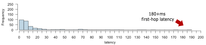
In fact, don't be surprised to see 100ms+ delays just for the first hop between the WiFi sender and the access point - e.g. see the histogram above, showing 180ms+ first-hop latency tails on my own (home) WiFi network. That said, note that there is no "typical" or "average" uplink WiFi latency: the latency will depend on the conditions and load of the particular WiFi network. In short, expect high variability and long latency tails, with an occasional chance of network collapse if too many peers are competing for access.
If your WiFi access point is also your gateway then you can run a simple ping command to measure your first hop latency.
Uplink scheduling on 4G networks
In order to make better use of the limited capacity of the shared radio channel and optimize energy use on the device, 4G/LTE standards take a much more hands-on approach to scheduling and resource assignment: the radio tower (eNodeB) notifies the device for when it should listen for inbound data, and also tells the device when it is allowed to transmit data. As you can imagine, this can incur a lot of coordination overhead (read, latency), but such is the cost of achieving higher channel and energy efficiency.
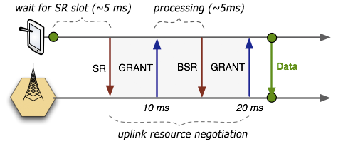
The radio network has a dedicated Physical Uplink Control Channel (PUCCH) which is used by the device to notify the radio network that it wants to transmit data: each device has a periodic timeslot (typically on a 5, 10, or 20 ms interval) where it is allowed to send a Scheduling Request (SR) that consists of a single bit indicating that it needs uplink access.
The SR request bit is received by the radio tower (eNodeB) but the SR request on its own is not sufficient to assign uplink resources as it doesn't tell the scheduler the amount of data that the device intends to transfer. So, the eNodeB responds with a small "uplink grant" that is just large enough to communicate the size of the pending buffer.
Once the device receives its first uplink grant, it waits for its turn to transmit (up to ~5 ms), and sends a Buffer Status Report (BSR) indicating the amount of application data pending in its upload buffers. Finally, the eNodeB receives the BSR message, allocates the necessary uplink resources and sends back another uplink grant that will allow the device to drain its buffer.
What happens if additional data is added to the device buffer while the above process is underway? Simple, the device sends another BSR message and waits for new uplink grant! If timed correctly, then the BSR requests and uplink grants can be pipelined with existing data transfers from the device, allowing us to minimize first-hop delays. On the other hand, once the device buffer is drained and then new data arrives, the entire process is repeated once over: SR, uplink grant, BSR, uplink grant, data transmission.
So, what does this all mean in practice? Let's do the math:
- If the network is configured to use a 10 ms periodic interval for communicating SR messages then we would expect a ~5 ms average delay before the SR request is sent.
- There are two full roundtrips between the device and the eNodeB to negotiate the uplink resource assignment to transmit pending application data. The latency incurred by these roundtrips will vary for each network, but as a rule of thumb each exchange is ~5 ms.
Add it all up, and we're looking at 20+ ms of delay between application data arriving at the (empty buffer) of the link layer on the device and the same data being available at the link layer of the eNodeB. From there the packet needs to traverse the carrier network, exit onto the public network, and get routed to your server.
Above uplink latency overhead is one reason why low latency applications, such as delivering voice, can be a big challenge over 4G networks. In fact, for voice specifically, there is ongoing work on Voice over LTE (VoLTE) which aims to address this problem. How? Well, one way is to provide a persistent uplink grant: transmit up to X bytes on a Y periodic interval. Believe it or not, today most 4G networks still fall back to old 3G infrastructure to transmit voice!
Optimizing for WiFi and 4G networks
As you can tell, both WiFi and 4G have their challenges. WiFi can deliver low latency first hop if the network is mostly idle: no coordination is required and the device can transmit whenever it senses that the radio channel is idle. On the other hand, WiFi is subject to high variability and long latency tails if the network has many peers competing for access - and most networks do.
By contrast, 4G networks require coordination between the device and the radio tower for each uplink transfer, which translates to higher minimum latency, but the upside is that 4G can reign in the latency tails and provides more predictable performance and reduces congestion.
So, how does all this impact application developers? First off, latency aside, and regardless of wireless technology, consider the energy costs of your network transfers! Periodic transfers incur high energy overhead due to the need to wake up the radio on each transmission. Second, same periodic transfers also incur high uplink coordination overhead - 4G in particular. In short, don't trickle data. Aggregate your network requests and fire them in one batch: you will reduce energy costs and reduce latency by amortizing scheduling overhead.
 Ilya Grigorik is a web ecosystem engineer, author of High Performance Browser Networking (O'Reilly), and Principal Engineer at Shopify — follow on Twitter.